
A Comprehensive Practical Manual for Computerized Cephalometrics in Orthodontic Practice
FMBODS • Second Edition
This manual presents the practical information necessary for the orthodontist to apply Computerized Cephalometrics in his practice. The technical details and scientific basis for the system are provided in other publications.
The manual consists of several sections.
Before the case is sent to FMBODS for analysis, certain information is normally recorded by the orthodontist from his clinical examination and/or plaster models.
a. Lips and mouth
b. Musculature
c. Arch form
d. Other history
A wax impression may be made of the lower arch using the special FMBODS plastic-backed wax wafer and sent to FMBODS. Remove the water from the plastic bag. Place the wafer in hot water for approximately one minute. Remove from the water and apply as one would a regular impression tray. Label it with the patient’s name. Replace it in the plastic bag. No special procedure is necessary in packaging the wafer, as the plastic tray protects it. Placing it in the plastic bag ensures that the wax will not mar the X-rays.
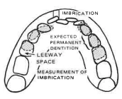
The wax wafer is used by FMBODS technicians for an arch length analysis by measuring imbrication. If deciduous teeth are present, a correction for “E” space will be made using Moyer/Wylie correlations between widths of incisors vs. canines and bicuspids at the 50 percent probability level, i.e., the error in the estimate is as likely to be on the high side as on the low side. The error for this method is usually within 2mm.
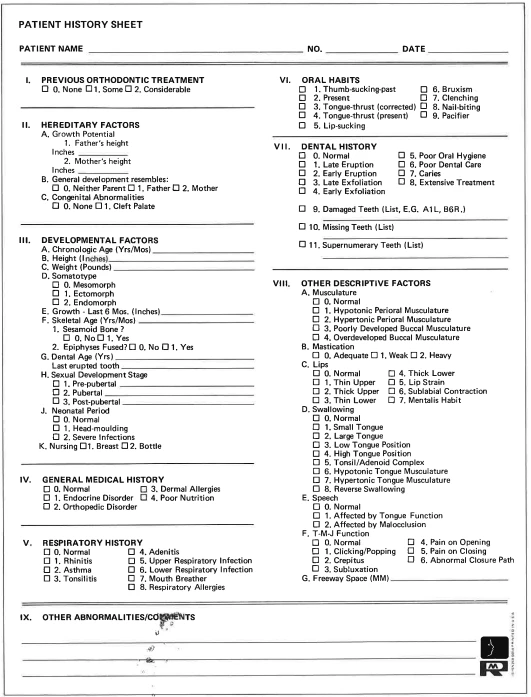
The history sheet is for the doctor’s use as a checklist and also to store extensive records for your data bank. It should be completed at the time of the clinical examination. It is optional and may be filled out partially, completely, or not at all, if preferred. The more data you feed into your data bank, the more value there will be in the future.
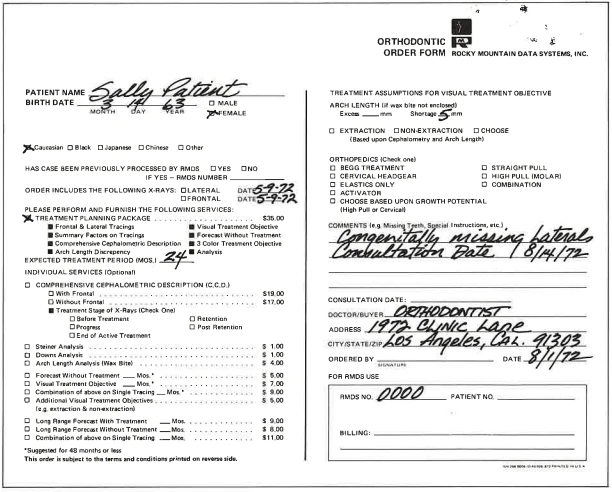
The illustration below shows a completed order form requesting only the materials discussed in this manual. Other materials will be discussed in other publications.
The order form requests birthdate, race, X-ray date, and the assumptions for the Visual Treatment Objective (V.T.O.).
You may specify the assumptions of the work-up, such as extraction, high pull headgear, if you wish, or have the computer formulate an assumption based upon the mechanical logic explained later on.
If you wish to perform your own arch length analysis rather than sending a wax bite, you must enter the resulting shortage or excess on the order form.
It is most important that the doctor note any missing or supernumerary teeth, or any other unusual circumstances, as it is easy to make errors in tracing if these are not recognized.
The frontal and lateral headplates are then to be sent along with the order form, history sheet and wax wafer in the blue envelope provided. You will receive materials for 20 cases initially and additional materials after every tenth case.
If necessary, a wrist plate may also be included to evaluate skeletal age. Assessing skeletal maturity can be valuable for patients when determining growth potential or when maturation timing is a significant factor in the clinical assessment.
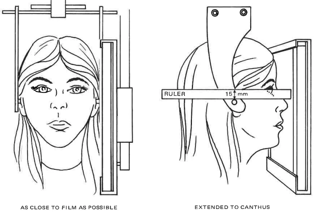
The illustrations below show the proper positioning for the frontal and lateral head-plates. The lateral assumes the patient’s cheek to be as close to the film as possible. The frontal should be aligned using a ruler. A line is scribed on the head holder 15mm above the ear rod and parallel to the ground. The ruler is used to extend this line to the canthus of the eye, as shown. Note that the patient’s face is closest to the film, thus giving a posterior - anterior (P.A.) film.
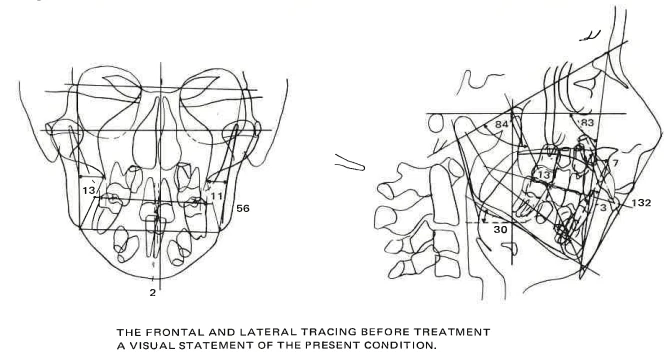
The first step in using the Data Systems materials is to quickly scan the tracing to get an overall feel for the case.
Seven lateral and four frontal factors are shown on the tracing. The lateral factors are:
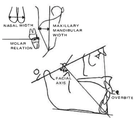
Facial axis - the angle between the Basion-Nasion plane and the plane from Foramen Rotundum to Gnathion - this gives the direction of growth of the chin.
Facial depth - the angle between the Frankfort plane and the facial plane N-Po.
Convexity - the distance between Pt A and the facial plane N-Po. This measures the horizontal relation between the upper and lower jaws.
Mandibular plane angle to Frankfort plane.
Lower incisor to A/Po - this gives the position of the lower arch in the jaw.
Upper molar position - the distance between the pterygoid vertical and the distal of the upper first molar.
Interincisal angle - the angle defined by the long axis of the central incisors. This gives the protrusion of the incisors.
The frontal factors include:
Intermolar width (lower arch).
Midline asymmetry - upper to lower incisor midlines.
Maxillo - mandibular width, right and left, to compare the relative widths of the upper and lower jaws.
This gives a basic description of the case today, and is the first step in the analysis.
The second analysis is the 50-factor comprehensive description. This is intended for an in-depth study of the problem areas. The use of individual factors will be discussed later.
You will notice that the factors in the printout (pg. 8-9) are given generalized conceptual names so that the actual points of measurement need not be memorized. The column "Clinical Deviations from the Norm" gives a degree of severity for each factor. The normal range is by definition -1 to +1, and severe abnormalities are those in excess of ±2. For consistency, we always measure the upper arch to the lower arch. A positive quantity indicates protrusion, prognathism, or mesial position as appropriate for each factor. A negative quantity indicates retrusion, retrognathism or distal position.
The norms are selected for the individual based upon age, sex, size (facial volume), and race.
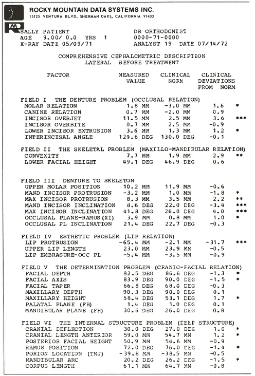
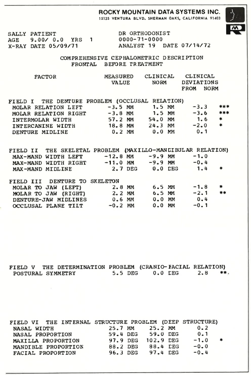
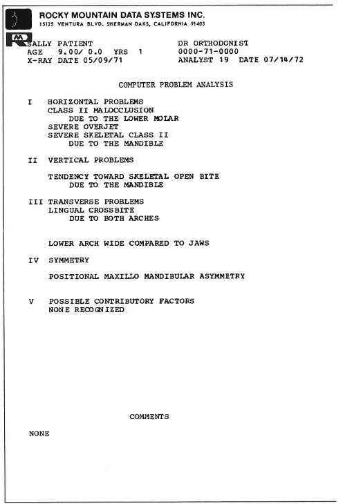
The real importance of the cephalometric measurements is in their use in pinpointing the problems of the cases:
Thus, the computer provides a cephalometric interpretation of the printout. We call it our Computer Problem Analysis.
It groups orthodontic problems into five classifications, i.e.:
Horizontal - Class II, Class III.
Vertical - Open and deep bites.
Transverse - Crossbites.
Symmetry - Midline shifts.
Contributory problems such as TMJ, lip sucking, and thumb sucking.
The analysis of each problem tells in words if there are cephalometric indications of the following:
Whether you have a malocclusion.
Whether the malocclusion is due to the lower or upper arch.
Whether the problem is skeletal.
Whether the skeletal problem is due to the lower or upper jaw.
This verbal discussion will be based upon an analysis of all 50 factors or more of the Comprehensive Cephalometric Description.
(See page for definitions of landmarks)
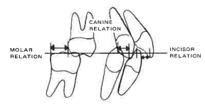
Is there a Class II, Class III malocclusion?
Measurement:
Molar relation
Canine relation
Overjet (Field I)
Illustration:
Treatment Implication:
Basic directions of treatment
Is the problem due to the upper or lower molars?
Measurement:
Upper molar position (Field III)
Illustration:
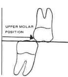
Treatment Implication:
Class II due to upper implies good non-ext. HG case. Due to lower implies would not want to move lower molar distally to gain arch length. Would prefer to treat moving lower forward.
Is the problem skeletal?
Measurement:
Convexity (Field II)
Illustration:
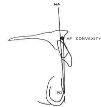
Treatment Implication:
If normal skeletal implies avoid use of headgear (Orthopedic force).
Is the skeletal problem due to the maxilla or mandible?
Measurement:
Maxillary depth
Facial depth
Confirmed by:
anterior cranial base length corpus length ramus position mandibular arc porion location(Field V & VI)
Illustration:
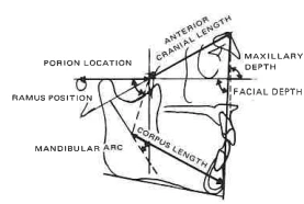
Treatment Implication:
Skeletal Class II due to maxilla implies good prognosis for HG early correction.
Due to mandible implies poor prognosis, try to minimize rotation during treatment. Class III due to forward ramus position and porion location implies probable excessive mandibular growth in future.
Is there a deep or open overbite?
Measurement:
Overbite (Field I)
Illustration:
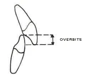
Treatment Implication:
Basic directions of treatment
Is it due to the upper or lower incisor?
Measurement:
Lower incisore
Extrusion (Field I)
Lip embrasure to occlusal plane
Illustration:
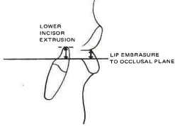
Treatment Implication:
Should the upper or lower incisor be intruded? (Check growth forecast for amount and direction.)
Is there an open or deep bite skeletal pattern?
Measurement:
Lower face height (Field II)
Illustration:
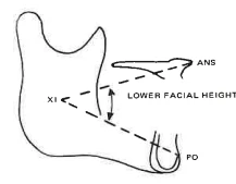
Treatment Implication:
Will growth be causing a problem in treatment? Is the dental problem skeletal?
Is the skeletal open or deep bite due to the maxilla or mandible?
Measurement:
Mandibular plane
Palatal plane
Maxillary height
Mandibular arc
Illustration:
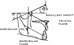
Treatment Implication:
Deep bite due to mandible implies cervical traction, open bite due to mandible implies high pull H.G., open bite due to tipped palate cervical H.G.
Is there a lingual or buccal crossbite?
Measurement:
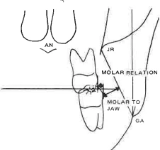
Molar relation left and right (Field I)
Treatment:
Basic directions of treatment.
Is the crossbite due to the lower or upper arch?
Measurement:
Molar to jaw left and right (Field III)
Treatment:
Lower arch width for this individual’s jaws implies a poor case for buccal expansion. (Unless the upper jaw can be widened.)
Illustration:
Is there a “skeletal” crossbite?
Measurement:
Maxillo-mandibular width left and right (Field II) confirmed by maxilla proportion and mandible proportion (Field VI)
Illustration:
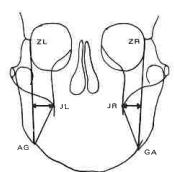
Treatment Implication:
Skeletal lingual crossbite implies orthopedic expansion
Crossbite not skeletal implies habit pattern must be alleviated and healthy oral environment created
Is the skeletal crossbite due to the maxilla or mandible?
Measurement:
Maxilla proportion
Mandible proportion
Illustration:
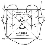
Treatment Implication:
Skeletal crossbite due to narrow maxilla better orthopedic expansion.
IV. SYMMETRY
Is there a midline shift?
Measurement:
Denture midline (Field I).
Illustration:
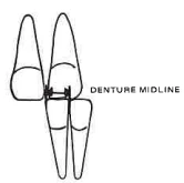
Treatment Implication:
Basic directions of treatment.
Is the shift dental discrepancy or a positional shift of the mandible?
Measurement:
Maxillo-mandibular midline (Field II).
Illustration:
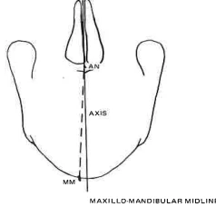
Treatment Implication:
Denotes degree of difficulty.
Is the asymmetry skeletal?
Measurement:
Occlusal plane tilt (Field III)
Postural symmetry (Field V)
Antigonial height
Illustration:
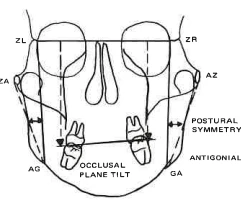
Treatment Implication:
Possible unilateral extractions or surgery. Should retake frontal to verify positioning if postural asymmetry.
POSSIBLE CONTRIBUTORY PROBLEM
Theory:
Low tongue position - causing a wide lower arch and narrow upper. The key is crossbite due to environmental rather than skeletal causes.
Measurement:
Molar relation (left and right)
Maxillo-mandibular width (left and right)
Molar to jaw (left and right)
Illustration:
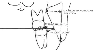
Theory:
Mouth breathing - similar to above with a narrow nasal cavity.
Measurement:
Nasal width
Plus the above measurements
Illustration:
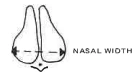
Theory:
TMJ growth problem - cephalometric clues are skeletal asymmetry, short ramus.
Measurement:
Posterior face height
Mandibular arc
Occlusal plane tilt
Postural symmetry
Illustration:
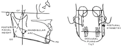
Theory:
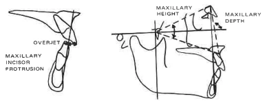
Thumb sucking - protrusive upper incisor, maxillary alveolar protrusion.
Measurement:
Maxillary incisor protrusion
Maxillary depth
Maxillary height
Overjet
Illustration:
Theory:
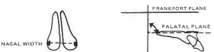
Microrhinodysplasia - palate tipped upward - narrow nasal cavity.
Measurement:
Palatal plane
Nasal width
Illustration:
Theory:
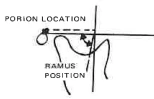
Pathologic Class III growth - this type tends to grow more in the mandible and less in the maxilla than normal.
Measurement:
Ramus position
Porion location
Illustration:
Theory:
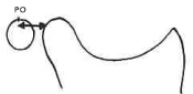
Condyle forward in fossa - false bite.
Measurement:
Distance from the distal of the condyle to the porion.
Illustration:
The service can make a preliminary selection among various treatment alternatives, assuming:
You would wish to have the treatment method that would tend to move toward the normal range.
You would prefer not to extract if the patient can be treated within the normal ranges without extraction.
The problem analysis then tells whether the following possibilities would be indicated, not indicated, or neutral:
"Neutral" implies that the cephalometric indications are neither clearly in favor of; or against the considered therapy. Therefore, considerations other than cephalometrics must form the basis of the decision.
High pull headgear - indicated on open-bite patterns, due to the mandible
Cervical headgear - indicated on deep bite patterns or cases where it is desirable to tip the palate.
Activator - indicated on deep-bite Class II with square jaws, retruded lower incisor when moderate convexity change is required.
Buccal expansion lower arch - indicates when the lower arch is narrow compared with the skeletal pattern.
Palate expansion - indicated when orthopedic expansion is desired.
Lower molar distal movement - indicated when the lower molar is forward, and more arch length is required. A maximum of 2mm may be suggested.
The service then provides an analysis of the factors involved in extraction:
Lower arch length shortage or excess - from the wax bite or supplied by you.
Effect of positioning lower incisor at +1 to A/Po after growth and convexity change (2mm arch length per mm incisor movement).
Effect of compromising convexity at the end of the normal range.
Possible compromise of the lower incisor depending upon the facial pattern.
Possible arch length gain through buccal expansion of molars and bicuspids to the end of the normal range (actually +.5CD on each side).
The total arch length shortage or excess after all compromises.
If there is still a shortage, the computer will assume extraction for your consideration. If excess, non-extraction in the lower arch.
The computer will then evaluate:
The predicted position of the upper molar, assuming non-extraction. If eventually there is not sufficient room for the second (12mm) and third molars (20mm) at the end of growth, it will indicate extraction in the upper arch*.
*Assumes average-sized teeth - smaller teeth will require less space.
The facial pattern will be evaluated. In a vertical pattern, less compromise of the incisors from the norm will be allowed; in a horizontal pattern, a more protrusive incisor will be allowed
The result is a readable summary of what cephalometrics has to say about the case
However, it should not be considered a complete diagnosis as many other factors, which are not cephalometric, must be evaluated in the final decision, such as musculature, tissue health, and cooperation. Further, while the FMBODS analysis is believed to be the most thorough analysis available, the interpretations may not agree with other cephalometric analyses based upon other reference frames.
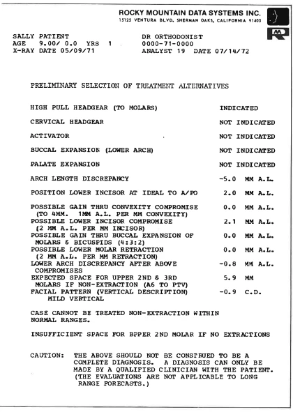
Choices of headgear.
Theory:
Headgear assumed in Class II if convexity reduction is desired.
Cervical is indicated in deep bite cases with a deep bite skeletal pattern, good horizontal growth expected or, if the palatal plane is tipped upward.
High pull is indicated in open bite cases with open bite skeletal patterns or vertical growth due to the mandible.
Measurements:
Overbite
Lower face height
Facial axis
Mandibular plane
Palatal plane
Posterior face height
Mandibular arc
Convexity
Molar relation
Illustration:
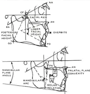
Activator.
Theory:
Activator recommended in deep bite facial pattern with square jaw, retruded lower incisor, moderate convexity, Class II.
Measurements:
Molar relation
Convexity
Lower incisor protrusion
Lower face height
Mandibular arc
Illustration:
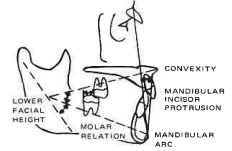
Buccal Expansion Lower Arch.
Theory:
Buccal expansion is preferred in cases with good growth potential and a narrow lower arch for facial type.
Measurements:
Molar to jaw (left and right) facial axis age.
Illustration:
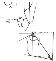
Palate expansion is preferred in cases of severe crossbite with a narrow maxilla and a narrow nasal cavity. Preferably in a deep bite pattern due to the tendency to open bite.
Theory:
Molar relation (left and right)
Maxillo-mandibular wide
Measurements:
Molar relation (left and right)
Maxillo-mandibular width (left and right)
Nasal width
Facial axis
Overbite
Illustration:
(PRELIMINARY SELECTION - Cont’d)
EXTRACTION—CONSIDERING FACTORS FOR INCREASING ARCH LENGTH
Arch Length Factor:
Lower arch length discrepancy (Model arch length)
Theory & Calculation:
Measured from wax bite - the total imbrication less spaces is calculated using calipers. If deciduous teeth, we use Wylie/Moyer correlation to estimate 3, 4, 5. Accuracy: Normally \(\pm \) 2mm for correlation.
Illustration:
Arch Length Factor:
Position lower incisor at ideal to A/Po. (Cephalometric Arch Length)
Theory & Calculation:
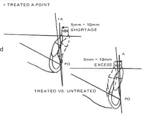
Each 1mm incisor movement changes arch length 2mm. Using a growth forecast, we locate the expected position of Pogonion and the desired position of Point A (maxilla) after treatment, and the new occlusal plane. The ideal position of the lower incisor is then 1mm ahead of the "ideal" A/Po plane. We then calculate the mm lingual or labial movement to achieve this ideal.
Illustration:
Arch Length Factor:
Possible gain through convexity compromise.
Theory & Calculation:
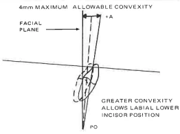
Each mm of retraction of Point A due to orthopedic force causes a \(1/2\)mm lingual movement of the A/Po plane at the occlusal plane. This necessitates a \(1/2\)mm lingual movement of the lower incisor to maintain a +1mm to A/Po and thus 1mm loss of arch length. Thus, if arch length is required, we may accept a more forward position of Point A. If necessary, the computer will accept a +4mm convexity maximum, if attainable.
Illustration:
Arch Length Factor:
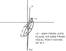
Possible gain through lower incisor compromise.
Theory & Calculation:
The normal range of lower incisor to A/Po is +1mm \(\pm \) 2mm or -1 to +3. We may, therefore, move the incisor to +3 to A/Po and gain 4mm of arch length still within normal ranges. The computer will accept a greater compromise in brachyfacial patterns, less in vertical patterns.
Illustration:
Arch Length Factor:
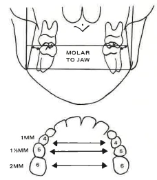
Gain through expansion of molars & bicuspids.
Theory & Calculation:
After evaluating the width of the lower molars to the jaws, the computer calculates the expansion allowable in molars to ᐩ ½ clinical deviation on each side. For each 4mm molar expansion, it assumes 3 mm second bicuspids and 2 mm first bicuspids for an arch length gain of 3 mm along the entire arch.
Illustration:
Arch Length Factor:
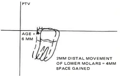
Possible gain through retraction of the lower molar.
Theory & Calculation:
Each mm lower 6 distal movement is 2 mm arch length gain. Computer calculates "norm" for lower molar and will allow retraction to 1½ mm distal to that norm (age 6 mm. A maximum of 2 mm will be suggested.
Illustration:
Arch Length Factor:
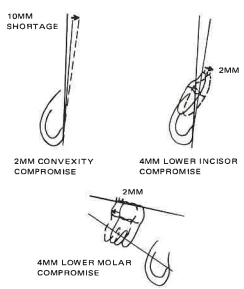
Total arch length discrepancy after compromise.
Theory & Calculation:
Gives the resulting shortage or excess if all above factors are compromised to limits of the normal ranges. "-mm" indicates the case could not be treated non-extraction within normal cephalometric ranges.
Illustration:
SPACE FOR UPPER MOLAR IF NON-EXTRACTION
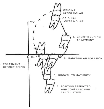
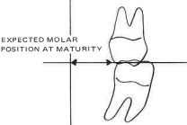
The distance at maturity between the pterygoid vertical (PTV) and the upper first molar is critical for the successful eruption of the upper second and third molars. There is less than a 10 percent chance of successful eruption of third molars if the distance is less than 20mm. Second molars require a minimum of 12 mm.*
The expected space available is calculated as follows:
The position of the lower molar in space is predicted for the duration of treatment with normal growth
This is corrected for mandibular rotation during treatment and,
Desired mesial or distal movement during treatment to give the expected position of the lower molar without treatment
The upper molar is then placed in a Class I to the lower and,
The amount and direction of growth to maturity of the upper molar is estimated to give the final expected position
The predicted position compared to the PTV is then calculated.
*Not applicable in cases with unusually small or large teeth
The next step in the FMBODS system is to arrive at a specific objective for this individual patient at the end of treatment, recognizing:
His expected amount and directions of growth.
The preliminary selection of treatment alternatives in Section III (orthopedics).
The expected result of the above on his growth pattern during treatment.
Arch length shortage.
A denture location and occlusion within the cephalometric "normal ranges".
Changes in the soft tissue profile due to tooth movement.
The ideal treatment objective is then an objective that has stood the test of logic; it places the plan on paper where you can visualize interrelationships to help you test your plan before beginning treatment. It must then be tested against other biological, cooperative, and mechanical factors by the orthodontist before a final diagnosis can be made.
SPECIFIC INFORMATION ON YOUR VTO
On your red VTO tracing (Growth Forecast with Treatment), you will find several items of information:
Displayed are two numbers in the form 24 months, 2.0 modules. The first refers to the number of months of growth requested. The second is the "equivalent" units of growth expected for this patient, based upon his age (preferably skeletal age) and sex. One module is equal to the average yearly growth of boys and girls between the ages of 8 and 13. Thus, 24 months, 3 modules might be typical for a boy during the spurt, 24 months, .5 modules would apply to a 14-year-old girl, 24 months, 2.0 modules to a girl age 9.
The label on the tracing gives the assumptions used in drawing up the V.T.O. by the technician. These will generally agree with the computer summary but will be rounded off to the nearest ½ mm.
While the computer may call for molar movement of "2.7", this is only for machine accuracy and is impractical.
One special situation should be noted. If the lower arch can be treated within normal ranges, but extraction is indicated in the upper arch, the doctor may wish to extract in the upper arch only, leaving the case in a Class II, or extract the second or the third molars, obtaining a Class I. This molar will be shown as a Class I on the forecast, but with diagonal lines indicating you may wish to leave it in a Class II.
The technician will also check the "reasonableness" of the computer assumptions in terms of treatment limitations. In addition, the final esthetic appearance will be evaluated, and if you give us special instructions, the decision to extract in borderline cases could be made according to your esthetic preferences, measured by the lower lip to the esthetic plane. We could change an extraction to a non-extraction if the profile is too flat (compared to the esthetic plane), or change a non-extraction case to an extraction if it is too full.
The lower lip to the E plane will form the basis of this evaluation.
HOW THE COMPUTER PREPARES A V.T.O.
Calculate the expected units of growth during the treatment period as a function of skeletal age and sex.
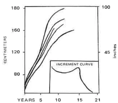
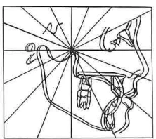
Grow the patient without treatment. (Each point has its own rate of growth & direction.) Establish assumptions of orthopedics - headgear, palate split, etc.
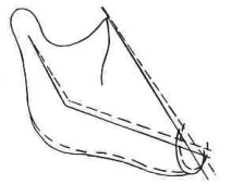
Rotate mandible for treatment effects due to the above, assuming non-extraction. The first trial by the computer is always non-extraction unless instructed by the doctor.
Select a reasonable objective for the maxilla accounting for growth, age, limitations of orthopedics, and cephalometric standards (2mm ±2mm convexity) based upon the expected position of the mandible. Draw the ideal A/Po plane.
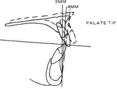
Change the occlusal plane if necessary to blend with the lip embrasure (computer will go halfway to the ideal).
Measure arch length discrepancy from models or wax bite.
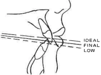
Position the lower incisor to "ideal" +1mm to A/Po, and 22°.
Calculate the effect on the arch length of "ideal" position.
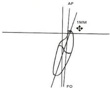
If the "model" arch length discrepancy plus ideal incisor position shows a resulting shortage, consider gaining arch length through:
Compromising convexity to +4mm, thus allowing a more forward A/Po plane and a more labial ideal position.
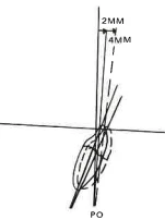
Compromising lower incisor to +3 (or as allowed by facial pattern)
Buccal expansion (see criteria)
You gain 1mm arch length with each
4mm Molar Expansion
3mm 1st bicuspids
2mm 2nd bicuspids
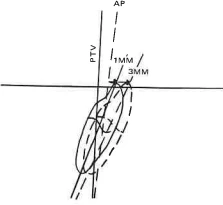
Lower molar distal movement (see criteria)
If the above will accommodate tooth mass within normal limits of lower molar and lower incisor positions, continue the non-extraction assumption; if not, assume extraction.
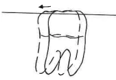
If extraction
Position the lower molar to account for arch length excess.
Assume loss of two lower bicuspids
(Average 14mm)
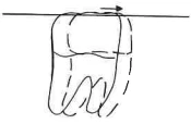
Reduce mandibular rotation for extraction. This assumes you use mechanics that prevent the eruption of the lower molars.
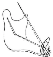
Place the upper molar in Class I to lower and extend the prediction to maturity.
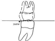
Check the upper molar prediction to PTV at maturity. Is there adequate room? If not, extraction in the upper arch may be indicated, due to probable interference with the 2nd and 3rd molars.
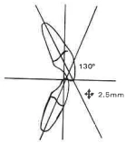
Place the upper incisor at a 2½ mm overbite and overjet and 130° to the lower.
Complete soft tissue to conform to tooth movement.
Check esthetics. Is the result too flat or too protrusive?
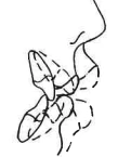
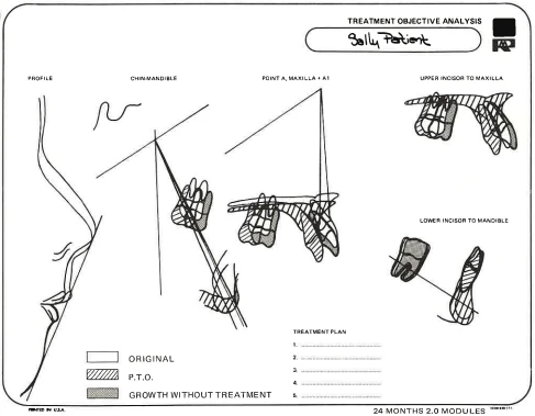
The essentials of the V.T.O. are displayed on the treatment objective analysis sheet. This overlay shows graphically where the patient is now (white), where he will be without treatment (shaded), and where you would have to treat him in order to obtain the objectives (stripes). On the actual overlay sent with the case, these are respectively: before treatment - blue; growth without treatment - green; treatment objective - red. It compares:
Profile change (superimposed on the esthetic plane).
Direction of growth of the chin and position of the upper molar (superimposed on the Basion-Nasion planes at PTV).
The maxilla (superimposed along Basion-Nasion at Nasion).
The maxillary dentition (superimposed on the palate).
The mandibular dentition is superimposed along the corpus axis at the pogonion.
It can be seen from this overlay what direction the mechanical force must take and whether natural growth will be working for or against the mechanical effect. Our subscribers have found this sheet to be the most useful aspect of the service for treatment planning and visualization of mechanics.
The next step is to accept or reject the V.T.O.
Can you accomplish the required movement mechanically?
Will the patient adapt to the new tooth positions?
Does the proposed treatment meet your esthetic requirements?
When you have decided on an objective that is desirable and feasible, you can then plan the mechanics necessary to achieve it.
You can visualize intrusion, distal movement, holding against growth, or allowing growth to do the work for you.
| SUPERPOSITION | EXPECTANCY WITHOUT TREATMENT | BEHAVIOR WITH TREATMENT - LIMITATIONS |
|---|---|---|
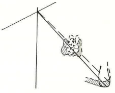
| Facial axis at the PT (pterygoid) point. | Mandible - grows directly down the facial axis.Upper molar - grows directly along the facial axis. | The mandible will rotate open with most normal mechanics. Can be closed by molar intrusion and/or extraction with mechanics to prevent molar eruption. Upper molar can be held or moved distally - Extrusion or intrusion depends upon the direction of pull if H.G. is used. |
ILLUSTRATION
| SUPERPOSITION | EXPECTANCY WITHOUT TREATMENT | BEHAVIOR WITH TREATMENT - LIMITATIONS |
|---|---|---|
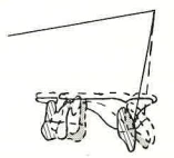
| Basion-Nasion at Nasion. | Maxilla grows directly down Nasion - A pt. line. Angle BA-NA does not usually change without treatment. | Angle BA-N-A can be reduced by 3-5° with orthopedic force. The palate will tip with heavy cervical traction. |
ILLUSTRATION
| SUPERPOSITION | EXPECTANCY WITHOUT TREATMENT | BEHAVIOR WITH TREATMENT - LIMITATIONS |
|---|---|---|
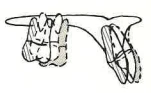
| Maxilla - Along the body of the maxilla at the incisive central. | Incisor erupts downward and forward - Arch length is maintained. | Incisor can be torqued and intruded as necessary. Requirements depend upon the growth of the mandible. |
ILLUSTRATION
| SUPERPOSITION | EXPECTANCY WITHOUT TREATMENT | BEHAVIOR WITH TREATMENT - LIMITATIONS |
|---|---|---|
| Corpus axis at Pogonion. | Molar erupts directly upward to the occlusal plane, and may come forward when E's are lost. Incisor erupts directly upward. | Incisor can be intruded as much as required, brought labially 3-6mm at the tip, lingually as much as required, molar can be moved distally up to 2mm. |
ILLUSTRATION
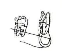
| SUPERPOSITION | EXPECTANCY WITHOUT TREATMENT | BEHAVIOR WITH TREATMENT - LIMITATIONS |
|---|
| Esthetic plane at the lip embrasure. | Lips recede at a rate of 1mm in five years. | Upper lip moves back with the upper incisor - Thickens 1/3 of the movement. The lower lip moves back with the point bisecting the overbite and overjet. Soft tissue A moves with A point. |
|---|
ILLUSTRATION
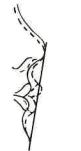
The fact that you have a specific roadmap telling you where you are now and where you want to be gives you a useful tool to monitor patient progress.
At 6-8 month intervals, a progress headplate can be taken. Using the Treatment Analysis overlays, there is no need to trace the progress headplate, nor take measurements. It will be sufficient just to lay the overlays on the progress headplate over a light box.
For short-range progress X-rays, you may substitute areas more easily seen than the areas of superposition used for long-range growth that might be difficult to locate on an X-ray, i.e., PT point, XI point, etc.
Thus, checking the progress of the upper molar and chin, you may superimpose on S-N at S. (You may have to pick a point between the red and blue nasions.)
To check the movement of the lower incisor and molar, you may superimpose on the symphysis.
To check the movement of the maxilla, superimpose on S-N at N if the basion is difficult to locate.
By visualizing where you are now, where you would be without treatment (normal growth), and the objective, you will be able to distinguish between lack of growth, poor reaction to mechanics, or lack of cooperation by noting whether progress is in the treated or untreated direction.
Finally, when the case is completed, the overlays will tell you how close the case came to the objective.
You can then consider the reasons and utilize the information in setting and accomplishing individual treatment objectives for future patients.
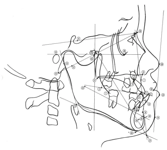
*) Point location not stored; used for QC measurement checks
| Code | Name | Definition |
|---|---|---|
| ① AP | A Point | The deepest point on the curve of the Maxilla between the anterior nasal spine and the dental alveolus. |
| ② A6 | Upper Molar | A point on the occlusal plane perpendicular to the distal surface of the crown of the upper first molar. |
| ③ A1 | Incisor | Incisal tip of the upper incisor. |
| ④ AR | Incisor | Root tip of the upper incisor. |
| ⑤ A3 | Cuspid | Tip of the upper canine. |
| ⑥ AN | Maxilla | Tip of the anterior nasal spine. |
| B6 | Lower Molar | A point on the occlusal plane perpendicular to the distal surface of the crown of the lower first permanent molar. |
| ⑦ BD | Lower Molar | A point on the distal surface of the crown of the lower first permanent molar. |
| ⑧ BP | B Point | The deepest point on the anterior curve of the mid-sagittal symphysis. |
| ⑨ B1 | Incisor | Incisal tip of the lower incisor. |
| ⑩ BR | Incisor | Root tip of the lower incisor. |
| ⑪ B3 | Cuspid | Tip of the lower canine. |
| ⑫ BA | Basion | The most inferior posterior point of the occipital bone. |
| ⑬ C1 | Condyle | A point on the condyle head that contacts the ramus plane. |
| ⑭ DT | Chin | The point on the anterior curve of the soft tissue chin, tangent to the esthetic plane. |
| ⑮ CC | Pterygoid | A point on the Basion-Nasion plane at the intersection of the PT-GN plane. |
| ⑯ CF | Pterygoid | Intersection of the Pterygoid Root Vertical with the Frankfort horizontal plane. |
| CR | Coronoid | A point at the center of the coronoid process neck, equidistant to the tip of the neck and to the posterior and anterior borders of the coronoid. |
| ⑰ DC | Condyle | A point selected in the center of the condyle neck on the BAN plane. |
| ⑱ DS | Symphysis | A point selected in the center of the symphysis by inspection. |
| Code | Name | Definition |
|---|---|---|
| ⑲ EM | Embrasure | A point where the upper and lower lips meet. |
| ⑳ EN | Nose | A point on the soft tissue nose tangent to the esthetic plane. |
| ㉑ GN | Gnathion | A point at the intersection of the facial and mandibular planes (Cephalometric GN). |
| ㉒ GO | Mandible | Gonion Intersection of the ramus and mandibular planes (Cephalometric GO). |
| ㉓ LL | Lip | Most anterior point on the lower lip (point closest to the esthetic plane). |
| ㉔ MM | Menton | A point located at the lowest point on the midline curve of the symphysis. |
| ㉕ NA | Nasion | A point at the anterior limit of the nasofrontal suture. |
| ㉖ OR | Orbitale | A point located at the lowest point on the external border of the orbital cavity, tangent to the Frankfort plane. |
| ㉗ PN | Maxilla | Tip of the posterior nasal spine. |
| ㉘ PO | Supra Pogonion | A point on mid-saggital symphysis at its anterior superior aspect, on a level with the end of the curved image of the symphysis cortical bone (horseshoe outline). |
| ㉙ PR | Porion | A point located at the most superior point of the external auditory meatus, tangent to the Frankfort plane. |
| PT | PT Point | Intersection of the inferior border of foramen rotundum with the posterior wall of the pterygomaxillary fossa as viewed in the lateral head film (Pterygoid Plate). |
| R1 | Mandible | The deepest point on the curve of the anterior border of the ramus, one-half the distance between the inferior and superior curves. |
| R2 | Mandible | A point located on the posterior border of the ramus of the mandible opposite R1. |
| R3 | Mandible | A point located at the center and most inferior aspect of the sigmoid notch of the ramus of the mandible. |
| R4 | Mandible | A point on the lower border of the mandible directly inferior to the center of the sigmoid notch of the ramus. |
| RPSETIXI | MandibleSellaTI Point Mandible | A point on the lower border of the mandible directly inferior to the deepest curve on the anterior border of the ramus.The center of cella turcica, selected by inspection.Intersection of the facial and occlusal plane.Located by constructing four planes: two perpendicular to the Frankfort horizontal passing through points R1 and R2, and two parallel horizontal planes to the Frankfort through Points R3 and R4; then locating a center point (XI) within the rectangle. |
| PLANE | DESCRIPTION |
|---|---|
| FRANKFORT HORIZONTAL | A plane tangent to the superior border of the external auditory meatus and the inferior border of the orbital cavity, (PR, OR). |
| FACIAL PLANE | A plane through Nasion and Pogonion (NA, PO). |
| MANDIBULAR PLANE | The plane is tangent to the lower border of the symphysis and the lower border of the angle of the mandible. |
| PTERYGOID ROOT VERTICAL | The vertical axis is constructed as a perpendicular to Frankfort Horizontal through the Pterygoid Root at the highest posterior point on the outline of the Pterygoid Plates at the Pterygopalatine fossa. |
| RAMUS PLANE | A plane tangent to the posterior border of the Ramus at both the Condyle head and the angle of the Mandible. |
| OCCLUSAL PLANE | A plane selected from bisection of the overbite of the upper and lower first permanent molars. |
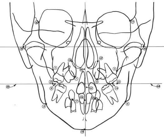
A3 - Cuspid (left) - Tips of upper permanent canines.
3A (right)
A6 - Molar - Bilateral points on the frontal occlusal plane perpendicular to the buccal surfaces of the crowns of the upper first permanent molars. A6 - left, 6A - right.
6A
AG - Mandible - Points at the lateral inferior margin of the antigonial protuberances. AG - left, GA - right.
GA
B3 - Cuspid (left) - Tips of lower permanent canines.
3B (right)
B6 - Molar - Bilateral points on the occlusal plane perpendicular to the buccal surfaces of the crowns of the lower first permanent molars. B6 - left, 6B - right.
6B
JL - Maxilla - Bilateral points on the jugal process at the intersection of the outline of the tuberosity and zygomatic buttress. JL - left, JR - right.
JR
MM - Menton/Mandible - Point on the inferior border of the symphysis directly inferior to the mental protuberance and below the center of trigonium mentali.
NC - Nasal - Points on the outline of the nasal cavity at the widest area in frontal perspective. NC - left, CN - right.
CN
ZL - Zygomatic - Zygomatic Bilateral points on the medial margin of the zygomatico-frontal suture, at the intersections of the orbits. ZL - left, ZR - right.
ZR
ZA - Zygomatic - Zygomatic-Center of the root of the zygomatic arch, mid-points. ZA - left, AZ - right.
AZ
AN - Anterior Nasal Spine - Tip of the anterior nasal spine just below the nasal cavity and above the hard palate.
1A - Point 1A - Selected at the interdental pappilia of the upper incisors at the junction of crowns and gingiva.
1B - Point 1B - Selected at the interdental pappilia of the lower incisors at the junction of crowns and gingiva.
Occlusal Plane - Selected from the bisection of the overbite of the upper and lower first permanent molars, both left and right sides.
* In all groups of two, the first entry indicates left, the second indicates right.
(Refer to Appendix for Mathematical Definitions of Factors and notations used.)